[RESULTS] The deformations of master and slave nodes of a rigid link are not exactly same. Why?
Creation date: 6/22/2016 6:50 PM
Updated: 9/5/2017 9:47 AM
The rotations of slave node must be the same as master node. But, the translational displacements of slave node
are not necessarily the same as master node because the rotation of master node will affect
the translational displacements of slave node.
Rigid Body Connection constrains the relative movements of the maste r node and slave nodes as if they are interconnected
by a three dimensional rigid body. In this case, relative nodal displacements are kept constant,
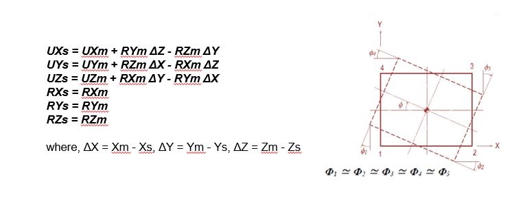
and the geometric relationships for the displacements are expressed by the following equations:

The subscripts, m and s, in the above equations represent a master node and slave node s respectively. UX, UY and UZ are displacements
in the Global Coordinate System (GCS) X, Y and Z directions respectively, and RX, RY and RZ are rotations about the GCS X, Y and Z-axes respectively.
Xm, Ym and Zm represent the coordinates of the master node, a nd Xs, Ys and Zs represent the coordinates of a slave node.
This feature may be applied t o certain members whose stiffnesses are substantially larger than the remaining structura
l members such that their deformations can be ignored. It can be also used in the case of a stiffened plate to interconnect its plate and stiffener.
Sample calculation of displacements of a slave node calculated from the displacements of
master node for a sample load is given below:
Distance between slave and master nodes:
X1 = -1.3725 + (0.05501) * (550) - (-0.00049) * (0) = 28.885 mm
Y1 = -0.02404+ (-0.00049) * (-210) - (-0.00022) * (550) = 0.20145 mm
Z1 = -1.4286 + (-0.00022) * (0) - (0.05501) * (-210) = 10.124 mm
are not necessarily the same as master node because the rotation of master node will affect
the translational displacements of slave node.
Rigid Body Connection constrains the relative movements of the maste r node and slave nodes as if they are interconnected
by a three dimensional rigid body. In this case, relative nodal displacements are kept constant,
and the geometric relationships for the displacements are expressed by the following equations:
The subscripts, m and s, in the above equations represent a master node and slave node s respectively. UX, UY and UZ are displacements
in the Global Coordinate System (GCS) X, Y and Z directions respectively, and RX, RY and RZ are rotations about the GCS X, Y and Z-axes respectively.
Xm, Ym and Zm represent the coordinates of the master node, a nd Xs, Ys and Zs represent the coordinates of a slave node.
This feature may be applied t o certain members whose stiffnesses are substantially larger than the remaining structura
l members such that their deformations can be ignored. It can be also used in the case of a stiffened plate to interconnect its plate and stiffener.
Sample calculation of displacements of a slave node calculated from the displacements of
master node for a sample load is given below:
| Node | DX (mm) | DY (mm) | DZ (mm) | RX ([rad]) | RY ([rad]) | RZ ([rad]) |
| Master | -1.3725 | -0.02404 | -1.4286 | -0.00022 | 0.05501 | -0.00049 |
| Slave | X1 | Y1 | Z1 | -0.00022 | 0.05501 | -0.00049 |
| ΔX (mm) | ΔY (mm) | ΔZ (mm) |
| -210 | 0 | 550 |
Distance between slave and master nodes:
X1 = -1.3725 + (0.05501) * (550) - (-0.00049) * (0) = 28.885 mm
Y1 = -0.02404+ (-0.00049) * (-210) - (-0.00022) * (550) = 0.20145 mm
Z1 = -1.4286 + (-0.00022) * (0) - (0.05501) * (-210) = 10.124 mm

